
01What actually changes?
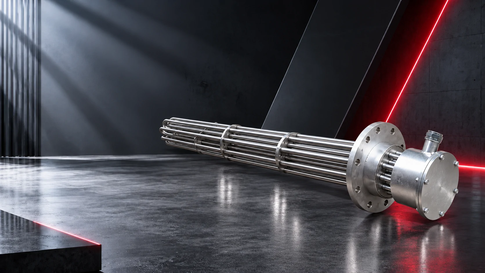
A flanged immersion heater bolts to a matching flange on the vessel or nozzle. A screw plug immersion heater threads into a matching opening or coupling. For a replacement, identify that connection before comparing heater ratings.
Flanges often accommodate larger assemblies and more elements, but power ranges overlap. Neither mounting style, by itself, establishes a pressure rating, corrosion allowance or hazardous-area approval. Those belong to the specific design.
02Compare the installation requirements
| Check | Flanged design | Screw plug design |
|---|---|---|
| Mating connection | Standard, nominal size, pressure class, facing and bolt pattern | Thread standard, nominal size, taper and sealing arrangement |
| Installation access | Bolt tightening and terminal enclosure access | Wrench access and any rotation needed during installation |
| Removal clearance | Clear axial space to withdraw the complete bundle | Withdrawal length plus clearance around the terminal enclosure |
| Operating suitability | Verify fluid, sheath, watt density, pressure and temperature | Verify the same factors; matching voltage and kW is insufficient |
03Insertion length is not the same as heated length
Ask the supplier to mark the unheated section and effective heated length on the drawing. The tank nozzle, insulation and minimum operating liquid level affect how much of the active section is actually submerged.
A heater can project into a tank while part of its active length remains inside a dry nozzle. Check the drawing against the lowest permitted liquid level, and specify suitable low-level protection and an independent high-temperature limit. Do not assume a universal cold-zone length.
04What to send for a replacement check
- Nameplate and wiring diagram: supply voltage, phase and rated kW.
- Mating flange drawing, or the exact thread standard and size.
- Insertion length, heated length, bundle diameter and sensor location.
- Fluid name and concentration, temperature, pressure and circulation conditions.
- Minimum liquid level, nozzle dimensions and available withdrawal space.
- Enclosure environment, cable-entry direction and required project approvals.
Mark unknown dimensions rather than guessing. Request an approval drawing before committing to a replacement. Photographs help identify a unit; they do not replace dimensional checks.
↗Sources and scope
References support the design principles discussed here. Product-specific limits must come from the selected equipment and fluid documentation. Illustrative values are not purchase specifications.