
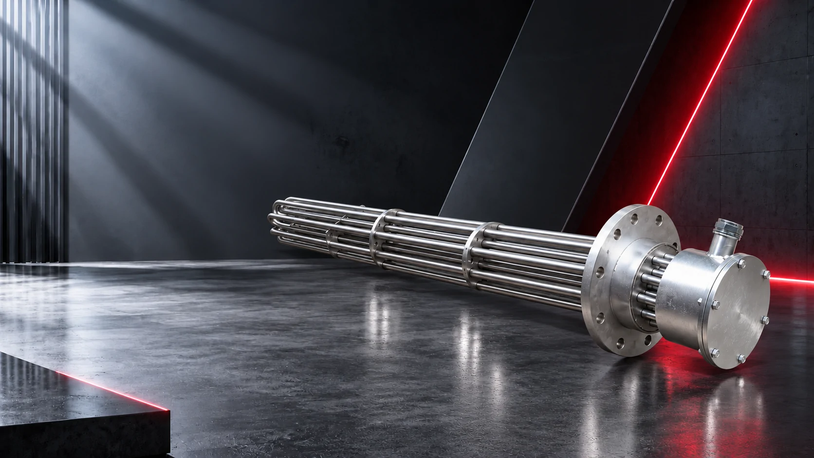
01Name the lengths clearly
The sheath length describes the metal tube. The heated length describes the section containing the active resistance-heating region. Unheated or cold sections connect that region to the terminals. “Cold” means no intended active heating in that section; it does not mean the surface remains cool. Heat can still conduct along the sheath and terminal hardware.
For a bent element, state whether a length is measured along the tube centreline or as a projected straight dimension. A U-shaped element’s insertion length is not the same as its developed tube length. Show the measurement datum at the mounting face.
02Mark these items on the drawing
| Dimension or feature | Why it matters |
|---|---|
| Mounting face to start of heat | Shows how the active section relates to the fitting or tank wall |
| Start and end of active section | Allows review of immersion or contact with the heated part |
| Bend centreline and radius | Defines the shape without treating the outside bend as a centreline |
| Terminal and lead clearance | Allows installation, enclosure and maintenance access |
03Do not assume a bend is unheated
A U-bend may be part of the active region, depending on the element design. Likewise, the straight section near a terminal may include an unheated length that is longer than expected. Obtain the manufacturer’s heated-length layout rather than inferring it from the visible shape.
Changing the cold-end lengths while holding total power constant can change the surface loading of the remaining heated section. It is therefore a design change, even when the outside dimensions remain identical. Have the supplier check both the electrical design and the application.
04Relate the active section to the installation
For immersion service, show the minimum operating liquid level and the intended orientation. For a heater inside a metal part, show the contact length. For air heating, show the air path across the active section. The same external shape can experience very different cooling in those installations.
Keep seals, terminals and lead insulation within their specified conditions. A longer unheated end may help the layout, but it is not a substitute for checking actual terminal temperatures, enclosure conditions and the supplier’s installation limits.
05Agree on one controlled drawing
Use a revision number and identify the mounting datum, active region, bend geometry and terminal arrangement. Ask the supplier to confirm these before manufacture. A marked drawing avoids repeat orders being made from an ambiguous measurement on an old part.
↗Technical references
Manufacturer references provide background. Use the approved drawing and instructions for the actual heater; the examples above are not purchase specifications.