
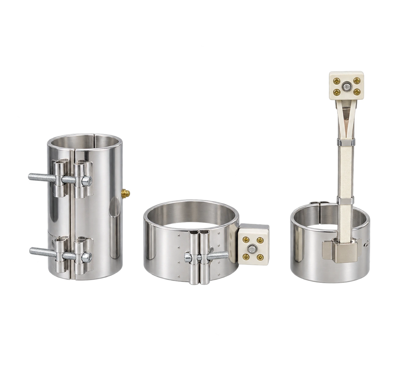
01Measure the barrel itself
Follow the equipment’s shutdown and cooling procedure. Measure the outside diameter at the mounting area and record any steps, grooves or wear. Check more than one cross-section if needed.
On a nearly round barrel, divide the measured circumference by pi to estimate the diameter. Provide a section drawing for stepped or irregular mounting surfaces.
02Measure usable axial width
Account for adjacent heaters, shoulders, flanges and clamping hardware. Record the old band’s width and the available width separately.
If a zone has two bands, show both widths and their gap. Do not use the combined width as the dimension for a single band.
03Mark holes and leads on a sketch
Use the barrel end or clamp opening as a reference. Mark sensor holes, bolt clearances, terminal direction and lead length. Include a scale in photos and identify the operator side.
Indicate whether the heater slides on from the end or must open around the barrel. Limited disassembly space can determine which construction fits.
04Include a nameplate photo
For each zone, list diameter, width, voltage, wattage, termination and quantity. Photograph the lead side and include a dimensioned view of holes or cutouts.
If the barrel is corroded, burred or distorted, have the mounting surface assessed before agreeing on tolerances and clamping.